McIntosh XRT18 Speaker System
A History
These pages are copyrighted.
No portion of this site may be reproduced in whole or in part
without written permission of the author.
![]()
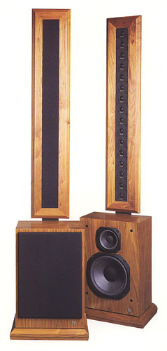 The XRT18 was a smaller lower cost column system
featuring low distortion and high power handling at high frequencies. It
contained a column of sixteen 1" soft dome tweeters that could be hung on
the wall or mounted on a stand. A 12" woofer and 6" mid-range were
used in the bass section. The optional base and stand are shown in the picture.
The XRT18 was a smaller lower cost column system
featuring low distortion and high power handling at high frequencies. It
contained a column of sixteen 1" soft dome tweeters that could be hung on
the wall or mounted on a stand. A 12" woofer and 6" mid-range were
used in the bass section. The optional base and stand are shown in the picture.
A tweeter column of this length was in the twilight area of near field and far field. It was neither a point source nor a column extending to infinity. The design problem was clearly audible with pink noise or program material. In the shallow near field, highs could only be heard when directly opposite some of the center tweeter elements. Even listening opposite to some of the end tweeters, differences could already be heard. In the far field the beam became even narrower but also exhibited lobe areas above and below the beam. Response in the anechoic chamber decreased at almost 6dB for doubling of distance indicating a point source behavior. A common crossover for all the tweeters was not practical as it was in the floor to ceiling column of the XRT20.
We concluded that some method of response or phase adjustment for each individual tweeter might be in order to widen the vertical response. Dr. Harry Olson demonstrated this idea to me when I visited with him at the David Sarnoff Research Center in Princeton, New Jersey many years ago. I was impressed with it at that time.
Carl developed a computer program to simulate the vertical behavior of columns. Using the variables of tweeter spacing, attenuation versus distance, directionality versus frequency, number of tweeters and wavelength for the frequency range covered by the tweeters, etc. there were a formidable number of solutions. Even after streamlining the program to leave out solutions that would be of no value, it required the use of a Digital Equipment super computer and 91 hours of running time. That was a big deal in 1983 and 1984.
We learned that the vertical directionality of the XRT18 could be improved by using four different crossovers for four different groups of tweeters. The top and bottom pair had one crossover, and the next inner pair had another, etc. The anechoic chamber enabled us to make polar plots at various distances and verify that Carl's solution was indeed excellent. This same idea of controlling response with individual tweeter crossovers was later put to use in the home theater three-tweeter array.
We had also constructed an array using Bessel functions as an alternate. However, Philips had a patent on this and management did not want to pay royalties for the use of it. The Philips U.S. patent number 4,399,328 “Direction and Frequency Independent Column of Electro-Acoustic Transducers” by N. V. Franssen was issued in August 1983 and assigned to the U.S. Philips Corp. The operation of the Bessel Array was well documented in papers titled “Multiple Loudspeaker Arrays Using Bessel Coefficients” by W.J.W. Kitzen and published in Electronic Components and Applications Vol. 5, No. 4 September 1983 and a paper titled “Effective Performance of Bessel Arrays” by Don B. Keele, Jr. presented at the 87th Audio Engineering Society Convention in October, 1989.
The XRT18 column was made of wood instead of the metal construction used in the XRT20. However, the width was kept the same. That controlled the tweeter rolloff at 1.5kHz. I confirmed by measurement that making the column narrower would not support the lowest tweeter frequencies and that making it wider gave too much low end. Tapering the width of the column from bottom to top was ruled out. That caused a change in response at different heights that could be easily heard and measured out in the listening area.
A listening test was made by comparing the old crossover to the new one using the same set of speakers. A multiple relay box with remote cable was used to switch the various crossover elements at the same time. The results of the new design were much improved. Standing and sitting were no longer like night and day.
![]()
Carl and I had learned very early that systems having the same size cabinet, driver locations, crossover response and driver response do not sound the same side by side. Crossover differences cannot be compared using two separate systems. The angle and distance to the listener is different for the pair of speakers A than for the pair of speakers B. The position in the room is also different for each pair of speakers. Speakers A can be located on the inside or outside of speakers B. They can be also located to the left or right of speakers B. Swapping speaker locations often results in the speakers at one location always having the same characteristic sound regardless of whether they are A or B. To properly A-B speakers, they must always be in the same position. However, comparison must also be instantaneous because we can't remember the sound accurately for any length of time. A method was needed to quickly remove one speaker and put the other in its place. Unfortunately, the accelerations needed to accomplish such a requirement would crush the speaker.
A side by side listening test casts a shadow on speaker comparisons in general. If identical speakers can't accurately be compared, then how can comparisons be accurately made against other drivers, cabinets or even other brands of speakers? The answer is that they can't be accurately made if the differences are very small or non-existent! Most speakers, however, do sound very different. This is due to different cabinet sizes, drivers, crossovers, driver orientation, directional response, etc. Side by side comparison is still valid, but will never be 100% accurate. Swapping locations during a listening test is still a good idea.
![]()
 The original prototype bass cabinet was a small
version of the XRT20 bass cabinet. The second prototype was changed to a
simpler construction for production. The XRT18 tweeter column could be easily
hung on a wall from a single strong picture hook. The matching CS 18 stand
later became available. The stand was attached to a pedestal made for the bass
cabinet.
The original prototype bass cabinet was a small
version of the XRT20 bass cabinet. The second prototype was changed to a
simpler construction for production. The XRT18 tweeter column could be easily
hung on a wall from a single strong picture hook. The matching CS 18 stand
later became available. The stand was attached to a pedestal made for the bass
cabinet.
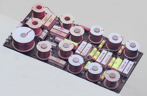
The crossover board was very large and complex due to the numerous parts needed for the four tweeter groups. The woofer was vibration isolated from the cabinet using a cast aluminum mounting ring and foam tape. Our research, using an accelerometer attached to the cabinet in many areas, showed that additional internal bracing did not effectively reduce cabinet vibration. It only shifted the areas of maximum vibration to other areas that were not braced. Our method of woofer vibration isolation virtually eliminated all cabinet vibration and any consequent secondary radiation from the cabinet surfaces.
Early versions of the XRT18 had a red and yellow indicator light mounted in the front of the bass cabinet at the bottom right. The yellow light was connected directly to the system input. It became visible when the input to the system approached rated power. It served only as a warning indicator. If the system was driven excessively hard, the main fuse would blow. If the system continued to be driven, the yellow light would still be seen but no sound would be heard. The red light was connected across the tweeter fuse. It could only be seen if the high frequency fuse was blown and the system continued to be driven at high power. Protection circuits were included for the lights.
![]()
I am pleased after all these years that my column solution to power handling and my patent has continued to be successfully marketed by McIntosh. It has been almost 30 years since I had constructed the first prototype. The advantages of the column in home systems are too good to ignore. See my page about my experience with columns.
![]()
|
|
|
After the design was completed, the work was far from finished. I prepared a bill of materials for the entire system. The bill of materials was divided into subassemblies. If new parts were used, I wrote out a new part number request describing the part and the vendor. For the crossover subassembly, I made a pictorial layout of the board, including the location of the holes, where solder lugs were to be riveted. There was also a wire list specifying the wire size, color, lengths and connectors. The woofer and mid-range were made by McIntosh and a separate bill of materials was required. The packing bill of materials was provided by engineering. I wrote the production test specifications for the crossover boards, drivers and finished systems. I also provided a sample wiring board for production. Production occasionally sent boards or drivers to the lab for testing if they were outside of the test of limits.
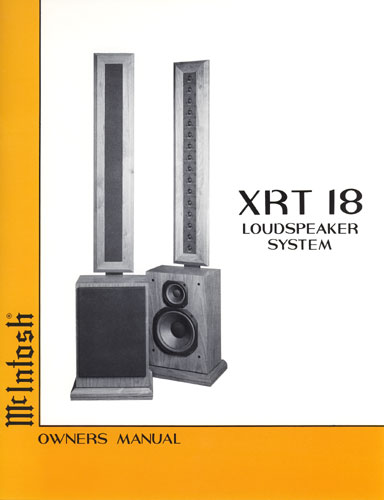
In addition to all of this, I was involved in writing the owner and service manuals. The owner’s manual contained a description of the design features and the system components. There was a brief description of the circuitry as well as the specifications. The service information contained schematic diagrams and pictorials of the crossover board. Specifications were also included.
There were often several printings of the owner’s manual. The cover appearance was sometimes changed and minor changes sometimes made to the text. There were sometimes changes made to the service information as well. If there was a change in the circuitry or parts, a new service information might be issued with the corresponding serial numbers indicated on the cover. If the changes were minor, a service bulletin was issued instead. Each issue of the manuals and bulletins could be identified at the back or on the bottom. For example, the back cover of this owner’s manual had the numbers 039-688.
![]()
I am pleased after all these years that my column solution to power handling and my patent has continued to be successfully marketed by McIntosh. It has been almost 30 years since I had constructed the first prototype. The advantages of the column in home systems are too good to ignore. See my page about my experience with columns.
![]()
XRT18 Specifications
Response: 20Hz to 20,000Hz
Power rating: 150 watts continuous, (300 watt occasional peak)
Output sensitivity: 86dB/watt/meter re: 8 ohms
Impedance: 8 ohms
Woofers: one 12" McIntosh
Mid-range: one 6" McIntosh
Tweeters: sixteen 1" custom soft domes
Crossover frequencies: 350Hz and 1500Hz
Overload protection: main and high frequency fuses
Finish: early version in walnut and later versions in walnut or oak
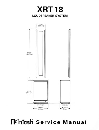
Dimensions: Bass section: 27-7/32" high, 17-1/2" wide and
11-3/4" deep
Dimensions: Tweeter column: 57-5/16 " high, 10-1/2" wide and
1-5/8" deep
Weight: Bass cabinet 63 lb.
Weight: Tweeter column 34 lb.
Sold from 1985 to 1992
Last retail price: $5398.00 /pair
CS18 Stand
Finish: walnut or oak
Shipping weight: 47 lb./pair
Last retail price: $600.00/pair
![]()
|
About This Site |
||
|
|
More text and pictures about McIntosh will be added as my research continues. Any comments, corrections, or additions are welcome. |
|
|
|
Created
by Roger Russell |
|