McIntosh XR250 Speaker System and LD/HP Woofer
A History
Copyright 1996-2005 by Roger Russell
All rights reserved
No portion of this site may be reproduced in whole or in part
without written permission of the author.
![]()
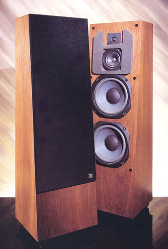 The XR250 is a continuation of our pet system, the
XR1051 and XR1052, which Carl and I spent so much time with at work and at
home. The improvement is mainly at low frequencies. Although the passive
radiator bass is very good, it does not extend down to 20Hz.
The XR250 is a continuation of our pet system, the
XR1051 and XR1052, which Carl and I spent so much time with at work and at
home. The improvement is mainly at low frequencies. Although the passive
radiator bass is very good, it does not extend down to 20Hz.
Carl had just completed his design of the LD/HP woofer and the XR250 is the first system to use this low distortion technology. I now consider this system to be the best of all the smaller McIntosh systems.
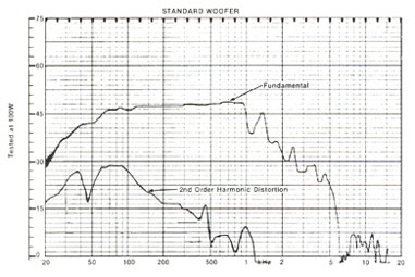
The distortion for the new woofer was measured using a Bruel & Kjaer 2020 slave filter and 1901 tracking frequency multiplier. A slow continuous sweep is made using a sine wave at 100 watts. That's right, 100 watts re: 8 ohms through the entire woofer range. Second order distortion remains less than 1%, and that's just for one woofer. Two are used in the XR250, which further reduce the distortion.
Two 10" woofers work better than one 12'' for several other reasons. The cone area is greater than for a single 12". Two voice coils can better dissipate heat. The 10" response better complements the 5" mid-range and the width of the enclosure can be made smaller.
Patent number 5,151,943 "Low distortion Dynamic Loudspeaker"
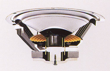 This is Carl's first patent and I am very happy for
him. The metal pieces above and below the magnetic gap have high electrical
conductivity. They serve to reduce effects of the voice coil magnetic field
interacting with the steel of the magnetic structure. The result is a very
significant reduction in distortion as well as lowering voice coil inductance.
We found that there were several other variations of copper or aluminum that
would work as well but at this time copper pipe was a very common material.
This is Carl's first patent and I am very happy for
him. The metal pieces above and below the magnetic gap have high electrical
conductivity. They serve to reduce effects of the voice coil magnetic field
interacting with the steel of the magnetic structure. The result is a very
significant reduction in distortion as well as lowering voice coil inductance.
We found that there were several other variations of copper or aluminum that
would work as well but at this time copper pipe was a very common material.
Of course, the McIntosh 5" mid-range and Philips 1" soft dome tweeter had already been proven to have low distortion. Over the years we found the soft woven textile dome tweeters to be superior to the metal and plastic dome tweeters. The Philips tweeter was custom made for McIntosh. I specified a special undercoating that was not their standard production. This damped out a resonance that would otherwise be significant.
My first listening session with the XR250 brought tears to my eyes. This didn’t usually happen with a new design that's fresh out of the anechoic chamber and reverberant room tests. The human voice with the LD/HP woofers was so clear it made the old woofers sound fuzzy and indistinct. As usual, the A-B switch was used for instant comparison of an XR250 with the old woofers and an XR250 with the new woofers. The A-B switch was in the audio line. It switched the preamp output between one stereo power amplifier (A) and another stereo power amplifier (B). The speakers remained permanently connected to each power amplifier. This avoided relay contact problems, particularly at high power. The gain of both amplifiers was carefully measured to be the same. I also had the acoustically transparent curtains closed so that I could be not distracted by visual clues. The choice was easy.
Being naturally cautious, I first thought the response of the woofers or the crossovers were different. Measurement in the anechoic chamber showed that the woofers and crossovers by themselves were too close to explain the difference, even where they were rolling off. The same went for the mid-ranges and tweeters. I had Carl reverse the position of the speakers behind the curtain in case it was one of those placement problems. The choice was still easy.
Carl and I had an understanding that when the other person is asked to switch something behind the curtains, unknown to the listener, we sometimes did not change what we said we did. It helped to make a double check on what the listener thought he was hearing. This time Carl had actually changed speaker positions as requested. It reminds me of the games Clouseau (Peter Sellers) played with his servant Kato in the Pink Panther movies. Sometimes this deception worked and fooled the listener. It usually worked best when the differences were very small or non-existent.
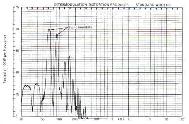
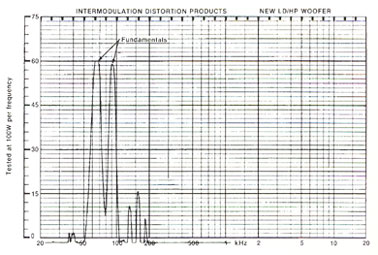
We even swapped woofers from one cabinet to the other, but the differences followed the woofers. I concluded that what I was hearing, which I thought was a difference in response, was actually the difference in distortion products. We then decided to measure IM distortion at a few pairs of frequencies. The old woofer measured 10% and the new LD/HP woofer was 0.5% under the same conditions. This kind of difference should be, and was, clearly audible.
![]()
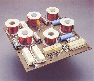 As a rule, we designed crossovers to complement the
normal response of the drivers. Driver response was not always flat in the passband.
Typically, crossovers such as Butterworth, Chebychev and Linkwitz-Riley are
nice as a starting point. However, the finished crossover didn't necessarily
resemble any of these. As in other McIntosh crossover designs, the components were
adjusted to produce the correct acoustic phase and response in the crossover
region. Passband adjustments were also made if necessary. Our measurements in
the anechoic chamber indicated there was very little change in response over a
wide listening area for the XR250. Although customers didn't normally listen in
an anechoic chamber, it enabled us to make the adjustments without interference
from reflected sound. This method of crossover design was perhaps more
sophisticated, but certainly more practical and produces better results.
As a rule, we designed crossovers to complement the
normal response of the drivers. Driver response was not always flat in the passband.
Typically, crossovers such as Butterworth, Chebychev and Linkwitz-Riley are
nice as a starting point. However, the finished crossover didn't necessarily
resemble any of these. As in other McIntosh crossover designs, the components were
adjusted to produce the correct acoustic phase and response in the crossover
region. Passband adjustments were also made if necessary. Our measurements in
the anechoic chamber indicated there was very little change in response over a
wide listening area for the XR250. Although customers didn't normally listen in
an anechoic chamber, it enabled us to make the adjustments without interference
from reflected sound. This method of crossover design was perhaps more
sophisticated, but certainly more practical and produces better results.
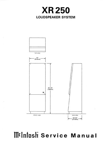
The XR250 had a slanted front. It was done primarily to move the center of gravity back so the system did not easily fall forward. Not everyone wants to use sharp spikes on their floors to accomplish this. Some people saw the slanted front as a means of adjusting the arrival time for the various drivers. It certainly didn't hurt the arrival time, but it was already well within the acceptable limits.
Acoustic foam was used around the mid-range and tweeter. This replaced the acoustic felt used in the XR1051/1052. The foam material reduced edge reflections at the higher frequencies and gave smoother response. The woofers were vibration isolated from the cabinet using cast aluminum mounting rings and foam tape. Our research concerning cabinet vibration employed an accelerometer attached to the cabinet in many areas. This indicated that additional internal bracing did not effectively reduce cabinet vibration. It only shifted the areas of maximum vibration to other areas that were not braced. Our method of woofer vibration isolation virtually eliminated all cabinet vibration and any consequent secondary radiation from the cabinet surfaces.
The XR250 was rated at 300-watts peak. Two bistable solid state current sensors were used in the system. A low current one protected the tweeter and a high current one protected the entire system. They could be easily reset by turning the volume down for 10 seconds. We tested the speakers for power handling with sine wave sweeps and also program material. One of my favorite power tests for prototype systems was to red light (power guard) the MC7270 (270 watts+) fifty percent of the time using rock music and drive the systems continuously all day for several days. Some favorite CD's were Meatloaf Bat Out of Hell, A-Ha Hunting High and Low and Pink Floyd A Momentary Lapse of Reason. The drivers and crossover had to survive. Actually, they sounded very good at this power level, just a little too loud for me, though. The amplifiers, of course, had no problem providing the power to do this all day.
|
|
|
After the design was completed, the work was far from finished. I prepared a bill of materials for the entire system. The bill of materials was divided into subassemblies. If new parts were used, I wrote out a new part number request describing the part and the vendor. For the crossover subassembly, I made a pictorial layout of the board, including the location of the holes, where solder lugs were to be riveted. There was also a wire list specifying the wire size, color, lengths and connectors. If the drivers were made by McIntosh, a separate bill of materials was also included. The packing bill of materials was provided by engineering. I wrote the production test specifications for the crossover boards, drivers and finished systems. I also provided a sample wiring board for production. Production occasionally sent boards or drivers to the lab for testing if they were outside of the test of limits.
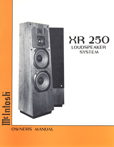
In addition to all of this, I was involved in writing the owner and service manuals. The owner’s manual contained a description of the design features and the system components. There was a brief description of the circuitry as well as the specifications. The service information contained schematic diagrams and pictorials of the crossover board. Specifications were also included.
There were often several printings of the owner’s manual. The cover appearance was sometimes changed and minor changes sometimes made to the text. There were sometimes changes made to the service information as well. If there was a change in the circuitry or parts, a new service information might be issued with the corresponding serial numbers indicated on the cover. If the changes were minor, a service bulletin was issued instead. Each issue of the manuals and bulletins could be identified at the back or on the bottom. For example, the back cover of this owner’s manual had the numbers 039-770.
McIntosh XR250 Loudspeaker System –Technical Paper (039-811)
“The Story Behind the New McIntosh XR250
During the past 20 years, McIntosh has developed a broad range of quality speaker systems dedicated to a simple, yet significant philosophy: To create speakers capable of duplicating the input signal as accurately as possible, over a broad listening area with superior imaging and low distortion.
Simple as this goal might sound, achieving it is an exacting combination of science, engineering, and art. McIntosh has invested heavily in test and research equipment to pursue this goal. The McIntosh Acoustics Design Laboratory in Binghamton, NY, includes a full size anechoic chamber, a specially designed reverberant room, a custom woodworking shop, and a controlled "blind" listening room. The McIntosh factory includes loudspeaker driver manufacturing facilities and a complete metal fabrication shop.
McIntosh designs and builds its own bass and mid‑range drivers. McIntosh tweeters are custom manufactured in Europe, and every one must pass a complete AQL (Acceptable Quality Level) battery of tests. In fact, every major component in a McIntosh loudspeaker including drivers, crossovers, and enclosures must pass a complete 100% Quality Assurance Inspection. Externally sourced components are subject to the same stringent Quality Control standards as those produced in‑house. McIntosh loudspeakers truly represent the finest of American engineering and craftsmanship.
McIntosh loudspeaker development and innovation has previously led to the granting of two patents covering unique loudspeaker technology. One patent involves active low frequency equalization for optimum performance in placement and in different rooms. The second patent covers design aspects of the XRT20 (since updated to the XRT22). Now a patent is pending for the unique LD/HP Driver technology included in the XR250.
Introduction
The McIntosh loudspeaker scientific team has decades of experience developing high quality loudspeakers. These men are notjust scientists, they are music lovers as well. Several years ago, they set out to build a speaker system for themselves. In addition to the basic McIntosh design philosophy outlined above, their design goals were further refined by the following additions:
Smooth, extended frequency response.
Exceptional dynamic capability.
Reduced overall distortion.
Superior dispersion characteristics for exceptional imaging stability.
An enclosure size and design to complement today's lifestyle.
In the time which followed, the team worked diligently, sometimes after hours and on weekends, to develop their "dream" loudspeaker. When their project was complete, McIntosh management had the opportunity to listen to the fruits of their labor. They were so impressed that they decided to bring it to market as the highly regarded McIntosh XR 1051 loudspeaker system. The XR 11051 (and its updated iteration, the XR 1052) has become an outstandingly successful loudspeaker produced by McIntosh.
Still, the development team continued to experiment to improve on the XR 1051/11052. Through all their best efforts (an endemic in all moving coil woofer designs), it was impossible to reduce Harmonic and Intermodulation distortion components to a level equal to the other elements in the system. Also, the team suspected that these distortion components were causing sonic anomalies beyond the bass and into the all important lower mid range.
The McIntosh Investigation
Their research involved building, testing, and listening to dozens of experimental driver configurations in order to accurately identify the source(s) of distortion. Materials were changed, surrounds and spiders dissected, voice coils wound and rewound. In fact, no component part of the driver was immune from their microscopic investigation. They eventually eliminated every aspect of the driver except the motor structure, the voice coil and magnet assembly, and the changing magnetic fields within.
Now, after two additional years of intensive research they have resolved this universal loudspeaker problem with a Fatent Fending driver design. Their efforts have resulted in the LD/HF Driver which reduces Harmonic and IM distortion components by over 90%.
The McIntosh investigation revealed that magnetic field interactions between the motor top plate, the voice coil, the ceramic magnet, and the pole piece, result in dynamic instabilities of the magnetic field surrounding the voice coil. Simply put, as the voice coil moves through the air gap, the magnetic field surrounding it varies due to the complex interactions of the magnetic and moving elements in the motor system itself. The voice coil then responds to this constantly changing asymmetrical magnetic field, producing substantial amounts of 2nd order HD and IM distortions (see charts I & 2 on back page).
Continuing research evolved a secondary and unexpected consequence of this effect. The electromagnetic interaction also appeared to cause impedance resistance changes in the voice coil. Should this prove to be true, there was a possibility the maximum power output of moving coil woofers was being artificially limited, which would naturally reduce the overall dynamic capability of the total system!
A moving coil or dynamic loudspeaker works in a very similar fashion to an electric motor. A coil of wire (the voice coil) is immersed in the gap of a strong magnetic field. The voice coil is to a loudspeaker what the rotor is to an electric motor. And the magnet structure is to the speaker what the stator is to the motor. When the audio amplifier sends an AC signal to the speaker, it passes through the voice coil causing a corresponding alternating magnetic field to be generated. This field forces the coil to move in and out in the magnetic gap as a result of the interaction of the two magnetic fields (that of the fixed stator field and that of the alternating voice coil, or rotor field).
Inside the driver motor strong magnetic fields are produced. The field produced by the formed ferrite ring magnet flows through, and is focused by the top plate, the bottom plate, the ring itself, and the pole piece. Other fields are generated by the amplifier current flowing through the voice coil and the motion of the voice coil in the strong magnetic field set up by the structure.
In effect the voice coil moving in the air gap of the motor structure is, in itself a generator, producing changing electrical and magnetic fields throughout its travel.
Dynamic loudspeaker drivers require a linear magnetic field in the gap surrounding the voice coil to reproduce sound with minimum distortion. This requirement becomes increasingly difficult to meet at low frequencies and high power levels. Contemporary design philosophy dictates that high quality woofers be designed with extended voice coils and deep magnetic structures to allow very large excursions for adequate dynamic range and power response. The asymmetry of magnetic flux in such a driver becomes severe as the voice coil moves through the gap center towards the extremes of its travel.
When the voice coil is driven to move within the magnetic air gap, the magnetic field within the gap becomes highly asymmetrical. This is due to the proximity and interaction between the magnetic fields generated by the voice coil as it moves, and another magnetic field generated across the air gap through the top plate and the pole piece. It is this magnetic instability which causes a driver to generate relatively high levels of 2nd order HD and IM.
Testing also proved the anticipated side effect of an overall reduction in driver output caused by impedance fluctuations in the voice coil to be true, and a direct consequence of the magnetic field asymmetry in the air gap. As the voice coil travels through the unstable magnetic field in the gap, the interaction of electrical forces and magnetic fluctuation causes changes in the impedance of the voice coil itself. This results in variations in level produced by the driver for a given amplifier input.
McIntosh engineers correctly surmised that shielding the voice coil from these magnetic flux interactions would accomplish the desired improvements: 1. Lower distortion levels and 2. Increase driver output. There followed a long series of testing and listening experiments to determine exactly what type of isolation system would achieve effective results. The McIntosh LD/HP Driver, for the first time, addresses these issues and solves the difficulties.
The McIntosh LD/HP Driver
McIntosh engineers attempted a number of logical design changes to eliminate the magnetic asymmetry by shielding the voice coil, all of which proved to be less than adequate. Eventually they determined that isolating the voice coil from the pole piece with a "sandwich" of non‑ferromagnetic highly conductive cylinders placed directly above and below the pole piece produced the desired effect.
Incorporating this cylinder shield design into an otherwise standard driver resulted in a reduction of distortion components by more than ILOdB (see charts 3 & 4 on back page).
The stabilization of the magnetic field also reduces variations in the voice coil inductance, thereby dramatically raising driver power output. The dynamic capability of this driver is unsurpassed and it is particularly well suited to the extended dynamic range available in digital source materials.
Listening to the XR250
The first product to incorporate the exciting new McIntosh LD/HP Driver is the XR250, a three way, four driver system with 2 10" LD/HP woofers, a 5" mid‑range driver and a I" dome tweeter. Extensive listening tests have confirmed the original theories of the McIntosh scientists: the XR250 bass response is deep, clean, and incredibly detailed. They were also correct in their assumption of an improvement in the lower mid range. The reduction in woofer IM distortion has produced a dramatic improvement in lower mid range clarity, definition, and imaging. Voices and instruments have an open, immediate sound quality which remains smooth and believable at any volume level.
The elimination of the dynamic limiting formerly imposed by the impedance changes in the voice coil has produced an effortless quality to the dynamic response of the system. More power simply makes it play louder, yet the sound remains smooth and effortless, never harsh or raspy as so typically occurs when even high quality speakers are pushed with very dynamic material.”
Distortion
|
Original woofer 2nd Harmonic
|
LD/HP Woofer 2nd Harmonic
|
|
|
|
|
Original Woofer IM
|
LD/HP Woofer IM
|

![]()
XR250 Specifications
Response: 20Hz to 20,000Hz
Power rating: 300 watts peak
Output sensitivity: 84dB/watt/meter re: 8 ohms
Impedance: 8 ohms
Woofers: two 10" McIntosh LD/HP
Mid-range: one 5" McIntosh
Tweeter: 1" custom soft dome
Crossover frequencies: 450Hz and 1300Hz
Overload protection: main and tweeter solid state current sensors
Finish: oak, walnut and black hardwood
Dimensions: 47-1/4" high, 14" wide and 7-7/8" deep at top,
12-5/8" at bottom
Weight: 81 lb.
Sold from 1991 to 1993
Last retail price: $2898.00 /pair
![]()
|
About This Site |
||
|
|
More text and pictures about McIntosh will be added as my research continues. Any comments, corrections, or additions are welcome. |
|
|
|
Created
by Roger Russell |
|