Jefferson Electric Testers
By Roger Russell
No
portion of this site may be reproduced in whole or in part
without written permission of the author.
![]()
Tube Checker
|
|
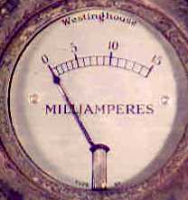
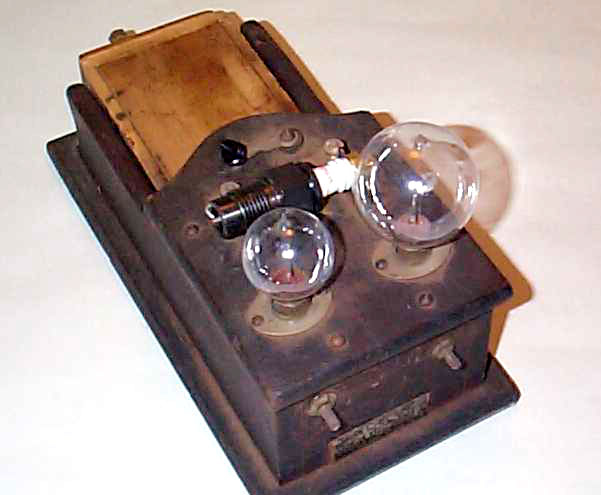
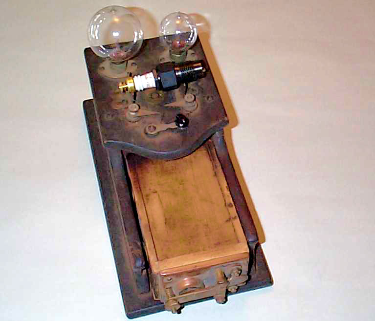
This early tube tester has sockets for two different size tubes. They're both 4 pin and have a bayonet type socket. The tester also has a Westinghouse 0 to 15 milliammeter. No model number for this tester is indicated. |
|
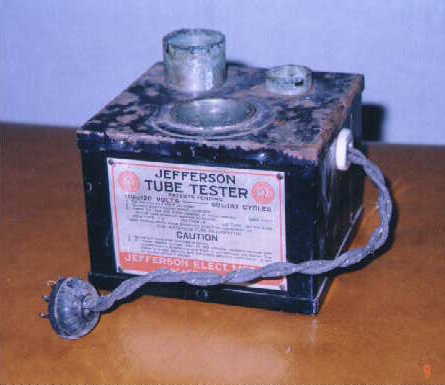
The tester comes with an 8" line cord made of two separate wires with black cloth on the outside. These are twisted together and exit the transformer case through a porcelain grommet that says Jefferson 100 1. The other end has an old style plastic two-prong plug. The bottom plate has four raised points near the corners. Size of the box is 4"H (4-7/8" including the sockets), 5-1/4"W and 5-1/16"D. For use on 110 to 120 Volts 50 to 133 cycles. Jefferson Electric Mfg. Co., Chicago, Illinois. Patents Pending. Weight is 3.9 lbs.
|
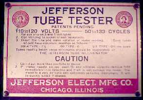
Instructions on the front plate are as follows: |
|||
|
1. For use only on 3 and 5 volt tubes |
|||
|
201-A Type - 7-1/2 |
199 Type - 6 |
UX Type - off the scale |
|
|
Tubes
reading below these minimums should be rejuvenated on |
|||
|
|
CAUTION 1. Do not put more than one tube in device. |
||
![]()
Tube Checker No. 290
Every
Set-Owner Needs One!
Tells You When Tubes Need Charging.
 The No. 290 Jefferson Tube checker is to your tubes
what the hydrometer is to your storage battery. It will test all tubes, large
and small, except the UV 199 type, which can also be tested by using an
adapter. Test shows good, fair or poor tubes. Poor and fair need charging. Full
instructions with each instrument. Case finished in crystallized green, trimmed
in nickel, and equipped with cord and plug. Size 5' long, 4" wide and 2-1/4"
high. Weight 1-1/2 lbs. List Price Each $6.00. ($8.50 list in Canada)
The No. 290 Jefferson Tube checker is to your tubes
what the hydrometer is to your storage battery. It will test all tubes, large
and small, except the UV 199 type, which can also be tested by using an
adapter. Test shows good, fair or poor tubes. Poor and fair need charging. Full
instructions with each instrument. Case finished in crystallized green, trimmed
in nickel, and equipped with cord and plug. Size 5' long, 4" wide and 2-1/4"
high. Weight 1-1/2 lbs. List Price Each $6.00. ($8.50 list in Canada)
![]()
Tube Charger No.275
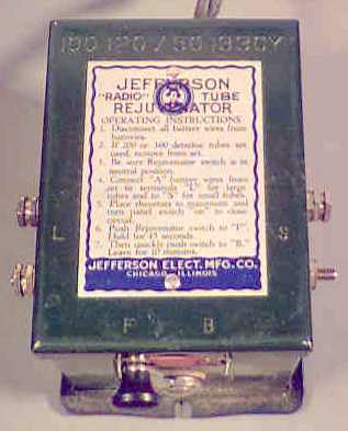 This is also called the "Radio" Tube Rejuvenator.
It comes with a 6-1/2 foot line cord made of two separate wires with black
cloth on the outside. These are twisted together and exit the transformer case
through a porcelain grommet that says Jefferson 100 1. The other end has an old
style plastic two-prong plug. The metal case is attached to a dish shaped
bottom plate that is raised around the perimeter. The case is dark green in
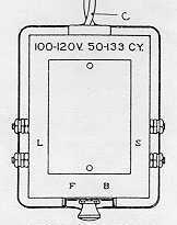
color. Terminals L are on the left and terminals S are at the right. Switch
position F is at the left front and B is at the right front.
This is also called the "Radio" Tube Rejuvenator.
It comes with a 6-1/2 foot line cord made of two separate wires with black
cloth on the outside. These are twisted together and exit the transformer case
through a porcelain grommet that says Jefferson 100 1. The other end has an old
style plastic two-prong plug. The metal case is attached to a dish shaped
bottom plate that is raised around the perimeter. The case is dark green in
color. Terminals L are on the left and terminals S are at the right. Switch
position F is at the left front and B is at the right front.
Size of the box is 3-3/8"H, 3-1/4"W (including terminals) and 4-1/8"D (including switch). For use on 110 to 120 Volts 50 to 133 cycles. Jefferson Electric Mfg. Co., 501-511 S. Green St., Chicago, Illinois. Weight is 3.4 lbs. Date on the instructions is November 1926.
Instructions for Operating No. 275 Tube Charger
Charging radio tubes with the JEFFERSON No.
275 is a simple matter and can be accomplished within twenty minutes whether
your set has one or a dozen tubes.
Simply attach the cord and plug (C) of Charger to any convenient alternating
current light socket or base board outlet of the voltage and frequency
specified on the instrument. Disconnect all set wires from the "A"
and "B" batteries.
Leave the tubes in their sockets in the set. Remove any 200 or 300 detector tubes from their sockets, because they cannot be charged, and will burn out if subjected to the high voltage of the flash (F). 200A or 300A need not be removed. Be sure that the switch (A) on the front of the charger is in the "off" position. (Not touching either contact) and that the panel switch of the set is turned "on" to close circuit.
Turn the rheostats of the set "full on" so that there is no resistance in the circuit. If you have filament ballast or self-adjusting rheostats in the set, remove them and short-circuit the gap by placing a piece of wire across the brackets.
Attach the two "A" battery wires to the two terminals marked "L" for charging the large 201A, 301A, UX171, and CX371 type tubes. To charge the small 199, 299, UX120 or CX220 type tubes, attach the "A" battery wires to the terminal marked "S".
Turn the switch to "F" and allow it to remain there for 45 seconds. Then quickly throw the switch to the contact marked "B" and leave it there for 20 minutes or longer.
When the 20 minutes are up, yank the cord (C) and disconnect the plug at the alternating current socket.
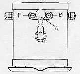
The current can also be disconnected by pushing the switch (A) on the Charger to "off" but care must be taken not to push it too far, for if you make contact with the flash contact "F" again, it will be necessary to charge the tubes all over again.
Only tubes having thoriated filaments can be charged. A few of the better known makes follow:
Radio Corporation of America-Type UV and UX199, UV and UX201A, UX200A and UXI 71; Cunningham C and CX299, C and CX301A, CX300A and CX371; Stewart-Warner; Diamond; Diatron; Radio Tube Corporation -- Type 2OIA; Sonatron -- Type 2OIA: Van Horne -- Model 5V-A; Musselman -Model 5VA: Ceco; Gold Seal; Puratone; Supertron; Sylvania; Yale; Kenrad; Electron.
Power tubes, UX120 and CX220 can be charged in a set having 199 and 299 tubes.
If you have a combination of 3-volt and 5-volt tubes in the same circuit, charge each voltage separately.
Suppose you have 199 tubes in the radio frequency circuit with 201A and power tube UX171 in the audio circuit, charge the 201A and UX171 first, removing the 199 tubes. Then remove the charged tubes and replace those to be charged. Be sure to change the "A" battery wires to the connections marked "S" for the 199 tubes.
Power tubes UX171 and CX371 can be charged in a set having 201A, 301A, 200A, or 300A tubes.
Power tubes UX112 and CX112 cannot be charged. Neither can WD11, WD12, WXI2, C11 and CX12 tubes. Attaching them to the Charger, you will burn out the filaments.
Curve Showing the Relative Amplifying Power Before and After Charging.
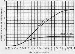 Tubes wear out with use. The fact that they still burn
is no indication of their ability to amplify the broadcast. After being in
service for a period, the thorium atoms, on the surface of the filament, which
carry the current to the plate, are consumed. There are more thorium atoms in
the tungsten filament, however, which can be brought to the surface by charging.
The chart above shows the difference between the amplifying power of a tube
fully charged and operating at highest efficiency, and a run down tube. Charge
your tubes once a month to keep them always at highest efficiency.
Tubes wear out with use. The fact that they still burn
is no indication of their ability to amplify the broadcast. After being in
service for a period, the thorium atoms, on the surface of the filament, which
carry the current to the plate, are consumed. There are more thorium atoms in
the tungsten filament, however, which can be brought to the surface by charging.
The chart above shows the difference between the amplifying power of a tube
fully charged and operating at highest efficiency, and a run down tube. Charge
your tubes once a month to keep them always at highest efficiency.
The vertical scale shows plate current in milli-amperes from 0 to 8. The horizontal scale shows grid bias volts from -12 to +12.
![]()
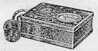
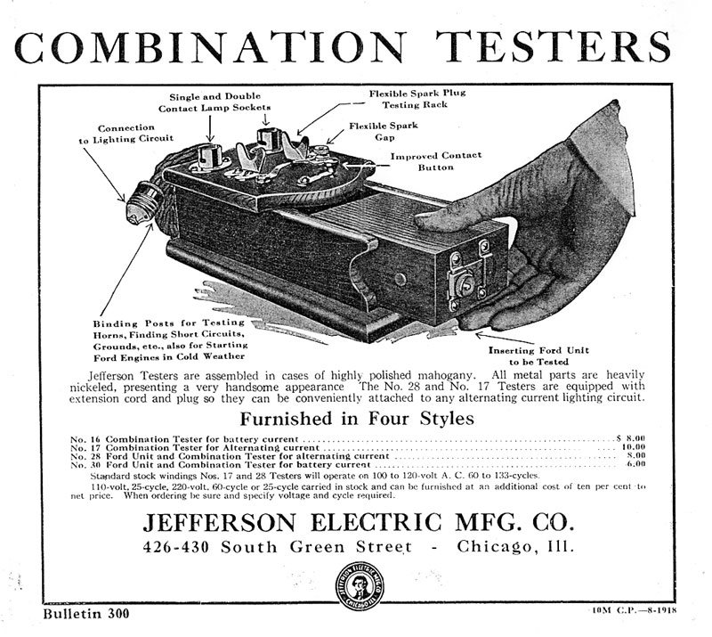
Jefferson Combination Testers
They are 4-1/2" high (including fixtures), 5-7/8"wide and 10-1/2"deep. Spark coils can be pushed into the opening at the top and connections are made with contacts on the inside of the tester. There are also sockets for testing lamps and spark plugs. Jefferson testers are assembled in cases of highly polished mahogany. All metal parts are heavily nickeled, presenting a very handsome appearance. The No. 28 and No. 17 testers are equipped with an extension cord and lamp socket connector instead of a normal two prong plug so they can be conveniently attached to any alternating current lamp.
|
About This Site |
||
|
|
More text and pictures about Jefferson will be added as my research continues. Any comments, corrections, or additions are welcome. |
|
|
|
|
All
contents are copyrighted |