Jefferson Electric & McIntosh Laboratory
By Roger Russell
Copyright
1996-2004 by Roger Russell
All rights reserved
No portion of this site may be reproduced in whole or in part
without written permission of the author.
An Interesting Comparison between Two Different Companies
|
|
|
|
![]()
What's on this page?
|
Introduction |
Jefferson 120 watt amplifier |
![]()
I wouldn't have thought there would be any connection between the two companies and truly there isn't but I have found a few similarities with respect to power amplifiers. Amplifier and transformer products made by older companies like Jefferson Electric have been long since discontinued and forgotten. They may be totally unknown by today's audiophile generation but they played an important role in audio reproduction back then.
It might seem strange that electrical technology was so far advanced for the 1910's and 1920's. Knowledge about coil properties, metallurgy, insulating materials, etc. was commonly known. The materials and production methods may not have been as sophisticated as what we have today, but the principles were the same and the products worked very well.
 My research
concerning McIntosh Laboratory is from what I learned when working there for 25
years designing loudspeakers. . A detailed account of this company can be found
on my McIntosh History Page.
McIntosh went into business in 1949 with the 50W-1 amplifier. It has a patented
unity coupled circuit and output transformer.
My research
concerning McIntosh Laboratory is from what I learned when working there for 25
years designing loudspeakers. . A detailed account of this company can be found
on my McIntosh History Page.
McIntosh went into business in 1949 with the 50W-1 amplifier. It has a patented
unity coupled circuit and output transformer.
 My research
into the Jefferson Electric
Company was inspired by my interest in the Golden Hour mystery clocks that
they made. Jefferson went into business in 1915 and made
bell-ringing transformers, toy train transformers and similar devices. By 1937,
they were making hundreds of different transformers. These include audio interstage,
auto-transformers, driver, line to grid, microphone, modulation, output, power,
speaker field supply, vibrator and choke coils. They supplied quality
transformers to such companies as Atwater Kent.
They also made a special line of audio output transformers for Jefferson
amplifiers.
My research
into the Jefferson Electric
Company was inspired by my interest in the Golden Hour mystery clocks that
they made. Jefferson went into business in 1915 and made
bell-ringing transformers, toy train transformers and similar devices. By 1937,
they were making hundreds of different transformers. These include audio interstage,
auto-transformers, driver, line to grid, microphone, modulation, output, power,
speaker field supply, vibrator and choke coils. They supplied quality
transformers to such companies as Atwater Kent.
They also made a special line of audio output transformers for Jefferson
amplifiers.
Jefferson amplifier circuits available in the 1930's were geared for PA sound systems and amateur radio use. The emphasis is on power output rather than extended response to 20kHz where it is not needed for these applications. The designs do not incorporate negative feedback that would have extended bandwidth and lowered distortion but at the cost of lower power output and/or more expense. Jefferson apparently did not sell complete amplifiers. They provided the designs, circuit diagrams, transformers, chokes and even a chassis and perforated cover. This marketing strategy was mainly to sell their transformers and chokes rather than get into the amplifier business. The power output for the amplifiers ranges from 12 watts to 120 watts.
Meanwhile, the radio broadcasting industry was expanding. In the 30's and 40's there appears to have been no limit on AM station frequency response. A response restriction was not even an issue at the time due to the limited bandwidth of most of the program material. In 1933 the FCC even expanded the AM band by allocating 1530, 1550 and 1570 for high fidelity stations. About 1937, FM broadcasting began. Response went out to 15kHz and even beyond. Although Jefferson was at the cutting edge of transformer design technology in 1936, it set the stage later for Frank McIntosh to develop the Unity Coupled transformer that enhanced power amplifier performance with wider bandwidth and lower distortion.
Both Jefferson and early McIntosh amplifiers use 6L6 output tubes. They both have driver transformers. Driver transformers are used in the first McIntosh designs like the 50W-1, 50W-2 and 20W-2.
The Jefferson amplifiers have what is called double channel input. The high level input goes to the 6N7 amplifier tube. The low-level input goes to the 6J7 preamplifier tube and then to the 6N7. The first McIntosh amplifiers have a similar application but a preamp tube assembly was sold as the plug-in accessory ACF-1. It includes a 12AX7 tube.
I also noticed the McIntosh part numbering system is the same as that used by Jefferson Electric.
|
McIntosh 50 watt Unity Coupled Amplifier Output: 50 Watts |
|
|
![]()
From Jefferson Literature
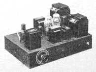
"This Jefferson amplifier circuit employs the new 6L6 beam power tube in push pull class AB2 to give a powerful 60 watt output with high power sensitivity and high efficiency. The output at all levels has low third and negligible higher order harmonic distortion and second harmonics are eliminated in the push pull circuit.
This circuit features the use of an unusual circuit arrangement with the D. C. obtained from two type 83 rectifier tubes. The power transformer has one set of windings for supplying both B current requirements for the initial stages of the amplifier and a steady source of fixed bias and screen voltages for the output stage. A steady screen voltage is absolutely essential to the satisfactory operation of the 6L6's at high output. The B current requirements of the output stage are supplied by another set of windings through an 83 rectifier. Choke input filter sections are employed in both rectifier circuits. Full power output is secured from the tubes.
The frequency response is practically flat from 30 to 12,000 cycles using either input channel. Input from either low or moderate level sources is controlled by a single center tapped potentiometer, which selectively controls the volume from either channel.
This amplifier uses the conventional Jefferson amplifier base and is simple to assemble and easy to wire. All components are liberally designed to insure superior and lasting performance"
|
Transformer No. 1 Cat. No. 463-541 Power transformer List Price $9.00 Amateurs: Cat. No. 467-526 Modulation transformer List price $9.00 |
![]()
From Jefferson Literature
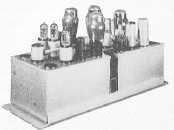
"A circuit comprised of four 6L6 beam power tubes in push pull parallel class AB2 has been designed by Jefferson engineers which utilizes to the fullest extent the capabilities of these new tubes. This output of 120 watts has been obtained with no sacrifice in either frequency response or stability of operation. Characteristic of the beam power tubes negligible harmonic distortion is present in the full 120 watts output.
Primarily designed for the amateur operator, this Jefferson amplifier gives more watts per dollar than other combinations of tubes and other component parts delivering the same power output. Two hundred and forty watts input to a class "C" amplifier can be modulated 100% with a quality, which approaches that of commercial stations.
A new feature presented in this, the latest of the Jefferson amplifiers, is a mixing circuit which permits the selection of either of two input sources or a combination of both. This circuit can be adapted to any Jefferson amplifier employing dual input channels.
One 83 rectifier and filter circuit provides a steady source of D.C. for the initial stages of the amplifier and the screen grids of the output tubes. A separate rectifier consisting of two 83 tubes in parallel and its filter circuit supplies the "B" requirements of the power tubes. Fixed bias for the driver and output tubes is obtained from a third rectifier and filter circuit which provides practically perfect regulation through the full output range of the 6L6 tubes."
Jefferson supplied a full schematic, parts list, transformers, chokes, two chassis and a cover. The amplifier could be made using either an output transformer or a modulation transformer.
|
Transformer No. 1 Cat. No. 465-261 Plate supply transformer List Price
$12.50 |
![]()
|
|
|
|
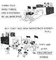
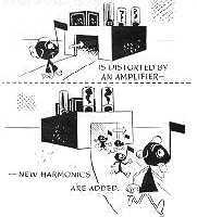
Some of you may remember the excellent and very humorous McIntosh advertising booklet titled Lost Instruments published in 1952. This explains the concept of distortion by using musical notes in illustrations. I picked up one of these at the New York Hi -Fi Show
Way back in the 1920's, Jefferson was using similar cartoon illustrations to explain performance of their transformers. This advertisement came from Popular Science Monthly, November 1926
|
|
|
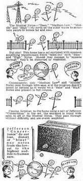
The Musical Notes--"Bass," "Medium-Low," Middle" and "High"--fly forth on the ether waves to entertain people in homes far and near. But alas! This home has a set equipped with common amplifying transformers which "fence out" both "Bass" and "High" notes. Should they manage to squeeze through, they'll be distorted or weakened. Consequently, only "Medium Low" and "Middle" notes pass through with ease, and the program doesn't sound as natural as it would were "Bass" and "High" notes also present in full volume. Coming, however, to the home using a pair of Jefferson "Concertones" in the set, the entrance is found wide open to all of the musical notes. They pass through without difficulty and are evenly amplified. Jefferson "Concertones" do not lose, distort or "blast" any notes from the lowest to the highest audible to the human ears. |
![]()
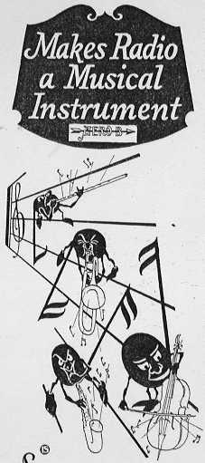
Here's another company that was using musical notes
The Glen L. Martin Company
Radio Division, Cleveland, Ohio
This advertisement is in the November 1926 issue of Popular Science Monthly
|
|
|
Deep
Resonant bass notes-vibrant high notes If you like music, you will want an Aero B Amplipower on your radio set. It brings out every note of every instrument as clear and full toned as the instrument itself. It makes any set a real musical instrument, reproducing the deep mellow bass notes that have heretofore been inaudible on practically all radio sets. The Aero B Amplipower not only improves tonal quality and increases volume but also supplies all of the "B" current for the set. It is attached to any set in the same manner as "B" batteries, with an adapter plug which is inserted in the tube socket of the last audio stage of the set, replacing this tube with the high voltage power tube in the Amplipower. |
![]()
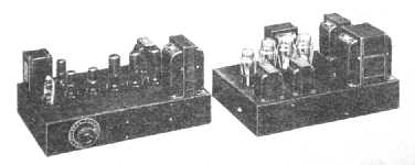
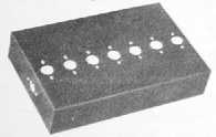
Jefferson Amplifier Foundation Unit
 "A
popular size one piece chassis around which all Jefferson
amplifier circuits are constructed. It enables the service man to build
powerful amplifiers of finished appearance and superior performance. A simple
yet effective foundation on which to economically build an amplifier of real
quality.
"A
popular size one piece chassis around which all Jefferson
amplifier circuits are constructed. It enables the service man to build
powerful amplifiers of finished appearance and superior performance. A simple
yet effective foundation on which to economically build an amplifier of real
quality.
It is a practically constructed base of heavy gauge (.050") sheet metal attractively finished on the outside in black baked crystal enamel. The inside is bright electro-galvanized to insure perfect grounding and easy soldering. The corners are reinforced and spot welded to form a unit of rigidity and strength. Each of the foundation units is provided with a series of socket holes, die punched along the central line, in which a standard wafer sockets can be mounted. Sockets with mounting holes on 1-1/2" to 1-29/32" centers can be fastened in the slots provided. With each foundation unit a template is supplied which gives the correct location of all the necessary parts and the holes for mounting them. The specific amplifier circuit for which the chassis is ordered determine which template shall be included.
Size 11" x 17" x 3-3/8" high. Weight 6 lbs."
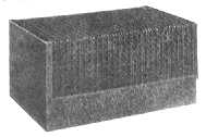 "To
protect the parts of the custom built Jefferson amplifier from
breakage and pilferage and to improve its appearance, an attractive cover is
provided which fits snugly over any of the above listed bases. it is made from
heavy gauge perforated metal and is finished with the same black enamel that is
applied to the bases. Provision is made for fastening it at the ends leaving
the sides of the chassis clear for any controls that are necessary.
"To
protect the parts of the custom built Jefferson amplifier from
breakage and pilferage and to improve its appearance, an attractive cover is
provided which fits snugly over any of the above listed bases. it is made from
heavy gauge perforated metal and is finished with the same black enamel that is
applied to the bases. Provision is made for fastening it at the ends leaving
the sides of the chassis clear for any controls that are necessary.
Size 11-1/4" x 17-3/8" x 6-3/8" high. Shipping weight 8 lbs. Cat. No. 469-201"
"Periodically complete circuit diagrams are published on powerful public address amplifiers which have been developed in the Jefferson Laboratory using various combinations of popular tubes. Jefferson engineers are well qualified through years of specialization in the radio transformer field to assume leadership in the promotion of custom built amplifiers among radio service men and experimenters. Careful study is given to the development of these special circuits--each is of proven performance--exclusive features abound and they are presented in simple and complete form. A wealth of testimonials declare to their popular acceptance.
When newly developed amplifier tubes are presented to the market their characteristics are carefully studied by Jefferson engineers and if found suitable a circuit is developed using them which is published in bulletin form and distributed to the trade. In this way the latest combinations are immediately made available.
It is customary to apply listed stock transformers and chokes to all new circuits wherever possible. A transformer or choke may have application to several circuits.
The components manufactured by Jefferson are listed at moderate price in spite of their superior quality. Quantity production under careful control and rigid inspection makes this possible
Copies of all amplifier circuits are available upon request."
From
Jefferson Radio Transformers and Chokes Catalog
No. 371-R July 1, 1937
|
Class B "59" Amplifier Power Output: 15 to 20 watts For tonal quality, fidelity of reproduction and exceptional volume this class "B" "59" amplifier is unsurpassed. A resistance coupled stage consisting of a "57" tube is employed to provide high gain. |
6A6 Convertible Amplifier Power Output: 20 watts This powerful convertible amplifier of practical construction is particularly well suited for public address work where the amplifier is to be adaptable for mobile duty operating from a 6 volt direct current source and as an AC amplifier using the 110 volts 60 cycle line as a source. |
|
2B6 Amplifier Power Output: 10 to 15 watts A circuit which realizes all the advantages of the 2B6 tube has been designed by Jefferson engineers to deliver 10 watts of audio power with an extremely flat frequency response. |
6F6 Amplifier Power Output: 18 watts This powerful amplifier uses the modern metal tubes--6J7, 6C5, 5Z4 and 6F6--in a circuit which gives a full 18 watts output with either a high or moderate gain input. |
|
2A3 Amplifier Power Output: 15 to 25 watts The amplifier is a development of the Jefferson laboratory and is designed to and actually develops the full listed output of the 2A3 tubes. |
6B5 Amplifier Power Output: 20 watts A circuit employing the popular 6B5 tubes in push pull to give a powerful 20 watt amplifier. The tremendous gain is secured by cascading triode connected 6C6's and a 6A6. |
|
P.P.P. "45" Amplifier Power Output: 38 watts Simple to construct and highly efficient in operation, this Jefferson foundation kit provides an economical and very suitable amplifier for use in large halls, schools and auditorium, and for small outdoor installations for amusement parks, baseball parks, dance pavilions, etc. |
6L6 Amplifier Power Output: 60 watts This Jefferson amplifier circuit employs the new 6L6 beam power tube in push pull class AB2 to give a powerful 60 watt output with high power sensitivity and high efficeincy. |
|
High Gain 2A3 Amplifier Power Output: 15 to 25 watts This modern amplifier circuit is a modification of the earlier "2A3" amplifier. The full power output of 15 watts normal is secured through the use of "56" drivers and the special Jefferson driver transformers. |
P.P.P. 6L6 Amplifier Power Output: 120 watts A circuit, the power output stage of which, consists of four 6L6 beam power tubes in push pull parallel class AB2 has been designed to utilize to the fullest extent the capabilities of these new tubes. |
![]()
|
About This Site |
||
|
|
More text and pictures about Jefferson and McIntosh will be added as my research continues. Any comments, corrections, or additions are welcome. |
|
|
|
Created by Roger Russell |
|