McIntosh Anechoic Chamber
A History
These pages are copyrighted.
No portion of this site may be reproduced in whole or in part
without written permission of the author.
![]()
Our new acoustics lab was finished in 1979 and included a large walk-in anechoic chamber. This was a most exciting time for me and was indeed a dream come true. My dedication to the pursuit of better sound could truly be fulfilled. The chamber provided the means to gain even more information and design even better systems than before. The purpose of an anechoic chamber is to provide a reflection free environment for acoustic tests. Although this is not like a home listening room, it allows us to measure just the speaker without interference from sound reflected from other surfaces. It enables us to design a system that works better in the typical home environment.
Sidney Corderman and I had looked at urethane foam wedges used at the Glendale IBM facility in Endicott. We learned that these wedges go into resonance at some frequencies and also tend to sag. An internal support was required. A further concern was for a fire hazard and the poisonous fumes that come from burning urethane. This in turn would necessitate a sprinkler system to be installed in the chamber. Fiberglass wedges are, of course, fireproof and no sprinklers were needed.
The cost for the parts for our chamber was $55,000. This did not include the cost of preparing the room where it was assembled. Gordon Gow believed this investment not only allowed us to be in a position of knowledge about our own products, but also about our competition. It was known to be the largest chamber in the industry that was devoted exclusively to the design of loudspeaker systems. It was also used to show visiting dealers and customers that we had a fully equipped sound laboratory.
The parts have arrived
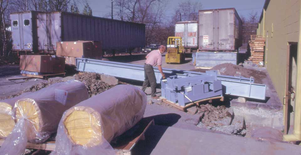
Parts and assembly were provided by Eckel Industries who were specialists in this business. The parts for the chamber arrived in four trailer trucks in the fall of 1979. They included four 12” steel I-beams to support the tensioned cable floor. Here is Earl Brown, who was employed by Eckel Industries, to assemble the chamber. With the aid of a fork lift, he removed the I-beams from one of the trucks. On a skid next to him are the steel supports that will hold the I-beams above the concrete floor. The door at the right of the picture led to the room that had been prepared for the chamber. With the aid of the fork lift, he maneuvered the beams through the door and then a palate lifter was used to raise them to the proper height. Later, the door and frame were removed and the opening was sealed with concrete block.
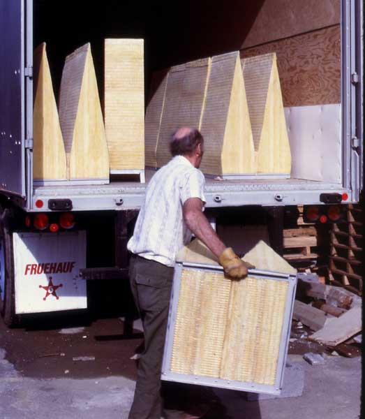 I have forgotten how many wedges were used to complete
the chamber. They were prefabricated in Canada. The fiberglass was packed to a
prescribed density and held in place by a wire mesh that is made up of 1/2 inch
squares. The mesh was attached to a square metal frame that stood on short
legs. These wedges were used on the floor. Other wedge assemblies had no legs
and were used on the walls and ceiling. The mesh had no effect on the sound
absorption of the wedges.
I have forgotten how many wedges were used to complete
the chamber. They were prefabricated in Canada. The fiberglass was packed to a
prescribed density and held in place by a wire mesh that is made up of 1/2 inch
squares. The mesh was attached to a square metal frame that stood on short
legs. These wedges were used on the floor. Other wedge assemblies had no legs
and were used on the walls and ceiling. The mesh had no effect on the sound
absorption of the wedges.
The fiberglass wedges were 54" deep and absorbed 99.9% of the sound energy striking them down to 1/4 wavelength, or about 65Hz. The wedges continued to absorb below this frequency but with less effectiveness. The angle and depth were both critical for maximum performance. The wedges were designed by Eckel. They were mounted on all surfaces of the room, including the door.
The floor above the wedges was woven out of stainless steel aircraft cable and spring tensioned to 150 lb. The cables were supported at the perimeter by 12" steel I-beams. The floor was 3-1/2" above the bottom wedges. The useable space in the chamber was 17'-11" by 11'-9" and 6'-4" high. The door was heavy steel with a double seal to insure maximum isolation from outside noise.
Concrete block was installed around the outside door frame so that it would be held firmly before the door was installed. The door was hinged on one side and the frame had to bear the weight of the door. Heavy triple hinges were used to support the door. A heavy meat locker type handle was used to secure the door. This implied that someone could be locked inside the chamber. An emergency push knob was installed so that the door could be opened from the inside.
The inner door also contained wedges so that when it was closed, you would be completely surrounded with wedges and there were no reflecting surfaces in the chamber. The door was located near one end of the chamber. The wedges were arranged on the door so they would mesh between the wedges of the adjacent wall.
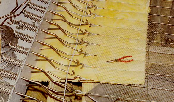 In the picture, you can see some of the many hundreds
of hooks used to hold the cables and how the springs are mounted to one of the
I-beams. If you were to add up the force contributed by all of the tensioned
cables, you can see why such large I-beams were needed. The pliers are in the
picture to give you a sense of scale.
In the picture, you can see some of the many hundreds
of hooks used to hold the cables and how the springs are mounted to one of the
I-beams. If you were to add up the force contributed by all of the tensioned
cables, you can see why such large I-beams were needed. The pliers are in the
picture to give you a sense of scale.
There was a slight bounce to the floor as you walked over it and it sagged only a small amount from your weight. One day, we had 20 Italian visitors in the chamber at one time and the cable floor still did not touch the wedges. A protective layer of ordinary window screening was placed under the cable floor. This was in case you drop something valuable, like your car keys! Otherwise, they could fall through the mesh of the floor and down between the wedges. The screen and cable floor had no effect on the absorption of the room surfaces.
 The room walls are made of concrete block. Earl used
explosive rivets to attach the brackets to the block wall. He said that a
license is required to have one of these guns. The wedges can then be hung on
the brackets and a ribbon of fiberglass is then filled in between them. Special
8 foot 300 lb sound absorbing silencers are used at the entrance and exit of
the air circulation system to prevent noise from entering the chamber. Earl
hired a temporary helper to do part of the assembly.
The room walls are made of concrete block. Earl used
explosive rivets to attach the brackets to the block wall. He said that a
license is required to have one of these guns. The wedges can then be hung on
the brackets and a ribbon of fiberglass is then filled in between them. Special
8 foot 300 lb sound absorbing silencers are used at the entrance and exit of
the air circulation system to prevent noise from entering the chamber. Earl
hired a temporary helper to do part of the assembly.
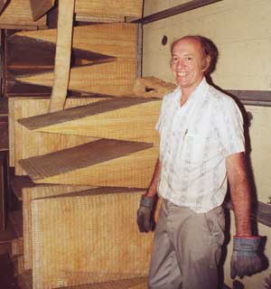
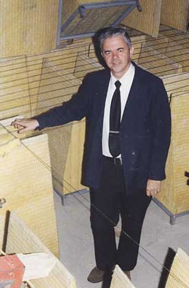 Here I am checking out the chamber construction that
is nearing completion in November. Some of the cables have already been
installed and can be seen behind me.
Here I am checking out the chamber construction that
is nearing completion in November. Some of the cables have already been
installed and can be seen behind me.
Several electrical conduits were installed on the concrete ceiling. Pipes were installed that came down between the wedges and had light sockets at the end. A flood light was used at each of these locations that would shine down to the floor. Electrical sockets were also installed between the wedges near the floor to run various pieces of equipment that might be needed. Wires for the microphone and speaker ran through a pipe in the wall to the test equipment located on a bench just outside the chamber.
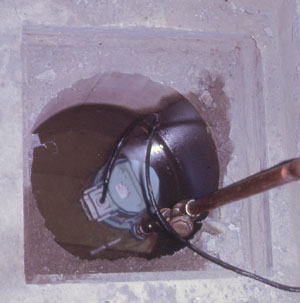 The chamber floor was constructed below the level of
the lab floor. When the original lab floor was removed to install the new
floor, water came in. It was necessary to install a drain to an outside
manhole, which housed a pump. If the water level in the manhole rose too high,
a float switch would turn the pump on. The water was then piped over to a
creek—the same creek that ran through my woods, far up the hill on Felters
Road.
The chamber floor was constructed below the level of
the lab floor. When the original lab floor was removed to install the new
floor, water came in. It was necessary to install a drain to an outside
manhole, which housed a pump. If the water level in the manhole rose too high,
a float switch would turn the pump on. The water was then piped over to a
creek—the same creek that ran through my woods, far up the hill on Felters
Road.
To supplement the pump action, I had a green light installed on the wall near the chamber that would go on when the pump was running. I also had a red light and a buzzer alarm installed to show when the water level got too high. On rainy days, particularly in the spring, the pump ran every few minutes.
Although we had a few pump failures, the water level never reached the height of the wedges. If water had reached the wedges, the absorption would be reduced drastically and it would take weeks for them to dry out
|
|
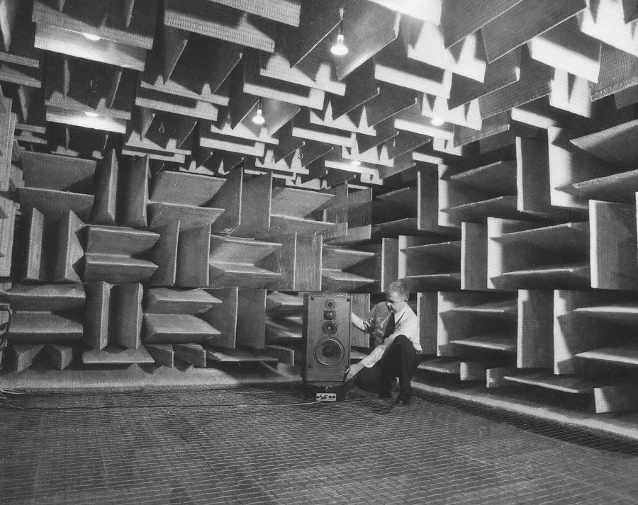
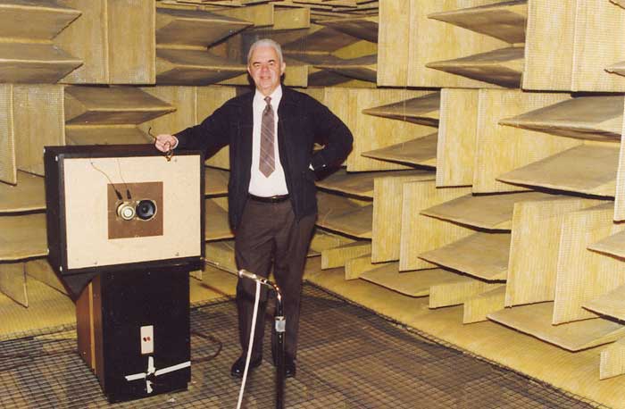
Here I am positioning the XR-16 on the Bruel & Kjaer turntable. A few wedges above the XR-16, and in the corner, you can see a vertical pair of wedges with the center cut out. This space leads to the air exhaust silencer. A similar arrangement at the opposite diagonal of the chamber is for the air input to the chamber.
All measurements in the anechoic chamber were made using the Bruel & Kjaer 4133 or 4149 free field microphones. The free field characteristics of the chamber were confirmed by placing a wide-range coaxial sound source at one end of the chamber and the microphone at the other end. By running a response curve at that point and then at half that distance, we found the response increased uniformly by 6dB. This indicates free field conditions. Reflection free response measurements could be made as low as 65 Hz.
The chamber was a very welcome addition and enabled Carl and I to gain further knowledge and make further design improvements. In addition, the B&K turntable was a big help in making polar response measurements. It turned in synchronism with circular paper on the chart recorder to automatically make a continuous curve. The speaker could be tested standing up for horizontal response or placed in its side for vertical response. It was particularly important in the design of the XRT20 and XRT18 tweeter columns. We were able to measure the characteristics of the long and short columns in both near field and far field. We measured the effect of tweeter spacing in the columns as well as many other variables that affected the performance.
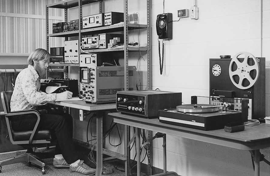
Test equipment is operated just outside the chamber. The speaker and microphone wires are run through separate conduits through the concrete block wall. Carl is making a polar response curve on the circular paper in the chart recorder. We also had a setup for measuring phono cartridges using Bruel & Kjaer test records, a Thorens turntable, SME arm and a C26 preamplifier. Arrival time measurements were made using a Tektronics delay sweep storage oscilloscope.
In addition to normal anechoic speaker measurements, we also made tests by adding reflecting surfaces, such as 4' X 8' sheets of plywood, to simulate the effect of a floor, corner or wall. It was interesting to observe the comb filter effect of adding a reflecting surface at one side of our XR1051 speaker system. If the plywood was then removed and a second but out of phase XR1051 system was placed where the mirror image for the plywood reflection was, the same comb filter effect could be measured.
The chamber gave us the opportunity to do unique listening tests. The speakers were placed at one end, spaced about 6 or 8 feet apart. We stood or sat at the other end. The speakers appeared to sound very different in this reflection free environment. We were isolated from outside noise and all room boundaries were essentially removed. The sensation was very similar to listening with headphones. It was easy to distinguish how the recordings were mixed. Some recordings had distinct blends of mono and reverb. Others presented a broad continuous sound stage, et cetera, et cetera. When the program material was deliberately switched to mono, and I stood directly in front of one speaker, even 10 or 12 feet away, the sound appeared to come only from that speaker and nothing from the other one. This was a good example of the precedence effect.
There was also a noticeable loss of bass compared to the listening room. First, the speakers could not be located against a wall or a floor. As a result, the speakers were effectively radiating into a 360-degree solid angle. There was no room gain. Second, there were no standing waves above 65Hz, but reflections were still reduced below that frequency.
We used the chamber to make measurements of the transformer vibration in some of the power amplifiers. The very quiet environment of the chamber was absolutely necessary. The sound level was so low that we had to keep absolutely still while moving the sound level around the equipment to be tested.
 Another interesting experiment was making high quality
recordings of musical instruments in the reflection free environment. This way
no "room sound" was included in the recording. A Tandberg 10XD
recorder was used for these tests. We could then play the recordings back
through the speakers being tested, either in the chamber or in the listening
room, and compare the reproduced sound to the live instrument. We used cymbal,
block, triangle, snare drum and violin. It was a nice idea. However, we learned
very soon that playing instruments exactly the same way each time was not
possible. Spectrum analysis of each strike or bowing revealed the differences.
Also, like speakers, musical instruments have directional properties. There
were good and bad locations to place the microphone. Although general
differences of the recorded versus real instrument could be heard, a precise
comparison was not practical.
Another interesting experiment was making high quality
recordings of musical instruments in the reflection free environment. This way
no "room sound" was included in the recording. A Tandberg 10XD
recorder was used for these tests. We could then play the recordings back
through the speakers being tested, either in the chamber or in the listening
room, and compare the reproduced sound to the live instrument. We used cymbal,
block, triangle, snare drum and violin. It was a nice idea. However, we learned
very soon that playing instruments exactly the same way each time was not
possible. Spectrum analysis of each strike or bowing revealed the differences.
Also, like speakers, musical instruments have directional properties. There
were good and bad locations to place the microphone. Although general
differences of the recorded versus real instrument could be heard, a precise
comparison was not practical.
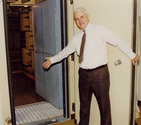
Visitors were very interested in seeing the new anechoic chamber. When the outer and inner doors were closed, you were completely cut off from outside sounds. In addition, there were no reflections of any sounds that you made in the chamber. It was total acoustic isolation. A few people were disturbed by the lack of acoustic stimulus in the chamber and wanted to get out. I thought it was very peaceful.
Does this picture remind you of an Alfred Hitchcock TV series program where visitors were invited to meet the chef that prepared an exotic meat dish called Lamb Amastrad—only to find that you are to be served AS the dish!
![]()
|
About This Site |
||
|
|
More text and pictures about McIntosh will be added as my research continues. Any comments, corrections, or additions are welcome. |
|
|
|
Created
by Roger Russell |
|