A Volume Compressor-Expander
By Roger Russell
Copyright 2005 by Roger Russell
All rights reserved
No portion of this site may be reproduced in whole or in part
without written permission of the author.
What Is On This Page?
The concept began 43 years ago in 1962. At that time it was difficult to find program material that was not compressed, either in the recording process or in broadcasts. Of course, it is understandable that technology at that time was more limited by noise at low levels and distortion at high levels. I had read in Radiotron Designer’s Handbook about connecting an incandescent lamp in series or lamps in a bridge circuit at the output of a power amplifier that could compress or expand a signal and decrease or increase the dynamic range delivered to the speaker. However, the lamp resistance in series with the amplifier output changed depending on the power to the lamp. This, in turn, affected the speaker response, which tended to then follow the ups and downs of the impedance curve. There must have been something better.
That’s when I got the idea of using a transistor that has relatively high input impedance compared to a lamp or a speaker and this would effectively isolate the lamp from the amplifier output. Then I could use a relatively small incandescent lamp to drive a photocell connected in a voltage divider circuit at the input to the amplifier. The photocell could be switched to increase or decrease the signal at the input to the amplifier. Louder passages would then play louder and softer passages would play softer. In the compression mode, the power delivered by the amplifier to the speaker could be limited. The amount of compression or expansion could be adjusted by changing values of the resistors in the voltage divider. I chose resistor values that worked well for music but greater compression or expansion could have been used as well.
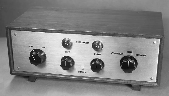
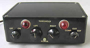
Stereo Compressor-Expander-
I made the first version in 1962. It was constructed using an aluminum chassis. I avoided making projects with a steel chassis because it was harder to work with. The front panel was made of brass that I brushed with fine sandpaper. I used brass only because I had some surplus pieces. Soldering steel angle brackets to the front plate made it easy to then attach the brackets to the aluminum chassis with screws. The cabinet was from a Sonotone CU-50 preamplifier. After applying the transferable decals, the whole panel was sprayed with a protective lacquer.
The threshold controls could be adjusted to the level where the user wanted the compression or expansion to occur. The lamps indicated the action of the signals and were wired in parallel with the lamps illuminating the photocells.
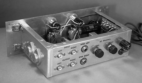
Rear View
The power transistors were mounted on the aluminum chassis and insulated with mica. In the back are the audio input and output jacks, speaker jacks, DC balance controls fuse, and line cord.
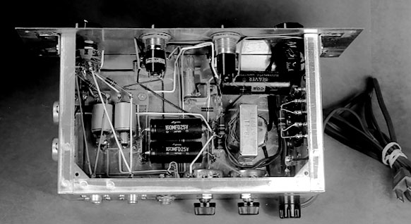
Top View
The lamp/photocell modules are at the left in the chassis. Filter capacitors for the power supply are in the center and the power transformer is at the right. A flat aluminum piece was used to cover the top.
![]()
Remote Volume and Balance Control
I also used this idea to control the volume and balance of my stereo system. Back in the early 60’s there were no infrared controls like we have today. The best thing available was an ultrasonic control used in some television sets like RCA and Admiral. Nothing like this was available for stereo systems. I do remember mentioning my enthusiasm for a remote control to Harry Norman at the New York Hi-Fi show. Harry worked for Fisher Radio. It was the next year that Fisher did come out with an ultrasonic remote control. However, these devices were not too reliable. The little electrostatic speaker in the transmitter was always having a problem.
|
|
|
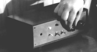
My hard wired remote was always reliable and a little easier to use. The principle here was simply to have a box between the preamplifier and power amplifier that had a photocell in a voltage divider connected the amplifier input. An incandescent lamp was contained in a small cylinder with the photocell. The DC voltage to the lamp was controlled through a long wire to a wire wound potentiometer in a remote control box. By varying the voltage to the lamp at the amplifier, the volume could be made to go up or down. To eliminate some of the variables, I used the left and right photocells in one module with the lamp in between. This way, I could control both channels at the same time.
For the balance control, I used another wire wound potentiometer plus a lamp/photocell module for each channel. Turning the potentiometer one way increased the brightness of the right lamp and turning the control the other way increased the brightness of the left lamp. The corresponding photocells controlled the volume in each channel. The box also had a switch that operated a relay at the remote location where the preamp and amplifiers were located and would turn them on or off. A second switch controlled power to other auxiliary equipment. Corresponding neon lamps at the front showed whether the power was on or off. LEDs were not commonly available back then.
Later, in the 1970’s, when 4-channel sound was making an appearance, I rebuilt the remote control and added front and rear balance controls. It could be used for either two or four channels. I decided the front panel should not have a brass appearance any more. I sprayed it black and then put on the transferable decals. Perhaps, by this time, I was thinking more of the black McIntosh panel appearance. I also sprayed the back of the aluminum chassis black and put on more decals. In this version, I eliminated screws showing on the front panel and attached the chassis to the cabinet at the bottom..
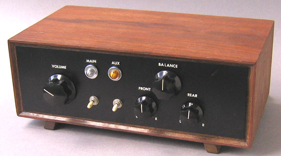
4-Channel Remote Control

Top View
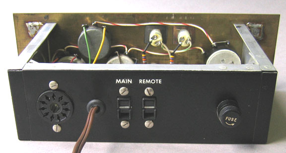
Rear View
An eleven pin socket was used at the rear of both two and four channel boxes to supply the DC voltage to be controlled by the potentiometers. The 120 VAC outlets went to relays to control the power to the remainder of the equipment at the remote location. I always used a fuse in all of my projects.
![]()
The Compressor-Expander Magazine Article
 I had no intention of writing a magazine
article about my accomplishment. However, after mentioning my device to Roland
Gray in the advertising department at Sonotone, He encouraged me to contact the
editor, Oliver Ferrell, at Popular Electronics magazine to see if he would be
interested in an article about it. When he expressed interest, I built a second
unit and selected a smaller plastic cabinet that was commonly available.
I had no intention of writing a magazine
article about my accomplishment. However, after mentioning my device to Roland
Gray in the advertising department at Sonotone, He encouraged me to contact the
editor, Oliver Ferrell, at Popular Electronics magazine to see if he would be
interested in an article about it. When he expressed interest, I built a second
unit and selected a smaller plastic cabinet that was commonly available.
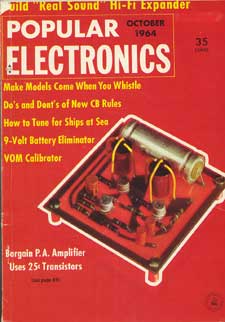
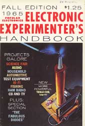 The article was published in the
October 1964 issue of Popular Electronics. It didn’t make the front cover but
it turned out to be so popular that it was reprinted in the fall 1965 edition
of the Electronic Experimenter’s Handbook. Julian Hirsch tested it and wrote a
very favorable report.
The article was published in the
October 1964 issue of Popular Electronics. It didn’t make the front cover but
it turned out to be so popular that it was reprinted in the fall 1965 edition
of the Electronic Experimenter’s Handbook. Julian Hirsch tested it and wrote a
very favorable report.
I received $200.00 for the original article and an additional $75.00 for the reissue.
In the reissue, I also provided a monophonic circuit for those who had expressed interest. I had earlier used the monophonic compression circuit in the power amplifier of my Schober electronic organ to limit the power that the amplifier delivered to the speaker.
The article is available in pdf format
You will need Adobe Reader to view it.
|
About This Site |
||
|
|
More text and pictures will be added as my research on this speaker continues. Any comments are welcome. |
|
|
|
Created
by Roger Russell
|
|